Product Description
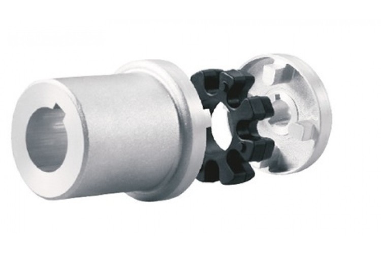
GIC-20×20 Shaft Flange Coupling Step Motor Flexible Coupling
Description of GIC-20×20 Shaft Flange Coupling Step Motor Flexible Coupling
>Integrated structure, the overall use of high-strength aluminum alloy materials
>Elastic action compensates radial, angular and axial deviation
>No gap shaft and sleeve connection, suitable for CHINAMFG and reverse rotation
>Designed for encoder and stepper motor
>Fastening method of clamping screw
Catalogue of GIC-20×20 Shaft Flange Coupling Step Motor Flexible Coupling
|
model parameter |
common bore diameter d1,d2 |
ΦD |
L |
L1 |
L2 |
F |
M |
tightening screw torque |
|
GIC-12xl8.5 |
2,3,4,5,6 |
12 |
18.5 |
0.55 |
1.3 |
2.5 |
M2.5 |
1 |
|
GIC-16xl6 |
3,4,5,6,6.35 |
16 |
16 |
0.55 |
1.4 |
3.18 |
M2.5 |
1 |
|
GIC-16×23 |
3,4,5,6,6.35 |
16 |
23 |
0.55 |
1.4 |
3.18 |
M2.5 |
1 |
|
GIC-19×23 |
3,4,5,6,6.35,7,8 |
19 |
23 |
0.55 |
1.4 |
3.18 |
M2.5 |
1 |
|
GIC-20×20 |
4,5,6,6.35,7,8,10 |
20 |
20 |
0.55 |
1.5 |
3.75 |
M2.5 |
1 |
|
GIC-20×26 |
4,5,6,6.35,7,8,10 |
20 |
26 |
0.55 |
1.5 |
3.75 |
M3 |
1.5 |
|
GIC-25×25 |
5,6,6.35,7,8,9,9.525,10,11,12 |
25 |
25 |
0.6 |
1.7 |
4.84 |
M3 |
1.5 |
|
GIC-25×31 |
5,6,6.35,7,8,9,9.525,10,11,12 |
25 |
31 |
0.6 |
1.8 |
4.46 |
M3 |
1.5 |
|
GIC-28.5×38 |
6,6.35,8,9,9.525,10,11,12,12.7,14 |
28.5 |
38 |
0.8 |
2.1 |
5.62 |
M4 |
2.5 |
|
GIC-32×32 |
8,9,9.525,10,11,12,12.7,14,15,16 |
32 |
32 |
0.8 |
2.3 |
6.07 |
M4 |
2.5 |
|
GIC-32×41 |
8,9,9.525,10,11,12,12.7,14,15,16 |
32 |
41 |
0.8 |
2.3 |
6.02 |
M4 |
2.5 |
|
GIC-38×41 |
8,9,9.525,10,11,12,14,15,16,17,18,19 |
38 |
41 |
0.8 |
2.7 |
5.32 |
M5 |
7 |
|
GIC-40×50 |
8,9,9.525,10,11,12,14,15,16,17,18,19,20 |
40 |
50 |
0.8 |
2.7 |
6.2 |
M5 |
7 |
|
GIC-40×56 |
8,10,11,12,12.7,14,15,16,17,18,19,20 |
40 |
56 |
0.8 |
2.7 |
8.5 |
M5 |
7 |
|
GIC-42×50 |
10,11,12,12.7,14,15,16,17,18,19,20,22,24 |
42 |
50 |
0.8 |
2.7 |
6.2 |
M5 |
7 |
|
GIC-50×50 |
10,12,12.7,14,15,16,17,18,19,20,22,24,25,28 |
50 |
50 |
0.8 |
2.9 |
7.22 |
M6 |
12 |
|
GIC-50×71 |
10,12,12.7,14,15,16,17,18,19,20,222425,28 |
50 |
71 |
0.8 |
3.3 |
8.5 |
M6 |
12 |
|
model parameter |
Rated torque(N.m) |
allowable eccentricity (mm) |
allowable deflection angle (°) |
allowable axial deviation (mm) |
maximum speed (rpm) |
static torsional stiffness (N.M/rad) |
weight (g) |
|
GIC-12xl8.5 |
0.5 |
0.1 |
2 |
±0.2 |
11000 |
60 |
4.8 |
|
GIC-16xl6 |
0.5 |
0.1 |
2 |
±0.2 |
10000 |
80 |
8 |
|
GIC-16×23 |
0.5 |
0.1 |
2 |
±0.2 |
9500 |
80 |
9.3 |
|
GIC-19×23 |
1 |
0.1 |
2 |
±0.2 |
9500 |
80 |
13 |
|
GIC-20×20 |
1 |
0.1 |
2 |
±0.2 |
10000 |
170 |
14 |
|
GIC-20×26 |
1 |
0.1 |
2 |
±0.2 |
7600 |
170 |
16.5 |
|
GIC-25×25 |
2 |
0.15 |
2 |
±0.2 |
6100 |
780 |
26 |
|
GIC-25×31 |
2 |
0.15 |
2 |
±0.2 |
6100 |
380 |
29 |
|
GIC-28.5×38 |
3 |
0.15 |
2 |
±0.2 |
5500 |
400 |
51 |
|
GIC-32×32 |
4 |
0.15 |
2 |
±0.2 |
5000 |
1100 |
56 |
|
GIC-32×41 |
4 |
0.15 |
2 |
±0.2 |
500 |
500 |
65 |
|
GIC-38×41 |
6.5 |
0.2 |
2 |
±0.2 |
650 |
650 |
107 |
|
GIC-40×50 |
6.5 |
0.2 |
2 |
±0.2 |
600 |
650 |
135 |
|
GIC-40×56 |
8 |
0.2 |
2 |
±0.2 |
800 |
800 |
142 |
|
GIC-42×50 |
8.5 |
0.2 |
2 |
±0.2 |
800 |
850 |
135 |
|
GIC-50×50 |
20 |
0.2 |
2 |
±0.2 |
1000 |
1000 |
220 |
|
GIC-50×71 |
20 |
0.2 |
2 |
±0.2 |
1000 |
1000 |
330 |
/* January 22, 2571 19:08:37 */!function(){function s(e,r){var a,o={};try{e&&e.split(“,”).forEach(function(e,t){e&&(a=e.match(/(.*?):(.*)$/))&&1
How to Select the Right Motor Coupling for Specific Torque and Speed Requirements?
Selecting the right motor coupling for specific torque and speed requirements is crucial to ensure optimal performance and reliability in a power transmission system. Here are the steps to guide you through the selection process:
1. Identify Torque and Speed Requirements:
Determine the torque and speed requirements of your application. Torque is the rotational force needed to perform the intended task, while speed refers to the rotational speed at which the coupling will operate.
2. Consider Operating Conditions:
Take into account the environmental conditions and operating parameters of your application. Factors such as temperature, humidity, and potential shock loads may influence the coupling’s performance.
3. Calculate Torque and Speed Ratios:
Calculate the torque and speed ratios between the motor and driven equipment. This will help you understand the required torque capacity and misalignment capabilities of the coupling.
4. Choose the Coupling Type:
Select a coupling type that aligns with your torque and speed requirements. For higher torque applications, consider gear couplings, while elastomeric couplings are suitable for lower torque applications with misalignment needs.
5. Check Torque and Speed Ratings:
Consult the manufacturer’s specifications to ensure the selected coupling can handle the calculated torque and speed requirements. Pay attention to both the continuous and peak torque ratings.
6. Misalignment Compensation:
If your application requires misalignment compensation, opt for flexible couplings that can accommodate angular and/or parallel misalignment.
7. Consider Critical Speed:
For high-speed applications, check the coupling’s critical speed rating. Operating near or beyond the critical speed can lead to resonance and coupling failure.
8. Verify Service Life:
Check the expected service life of the coupling under your application’s conditions. A coupling with a longer service life can reduce maintenance needs and downtime.
9. Budget and Cost:
Consider the budget and overall cost of the coupling, including installation and maintenance expenses. Balance the initial cost with the coupling’s expected performance and durability.
10. Seek Expert Advice:
If you are unsure about the best coupling choice for your specific requirements, consult with coupling manufacturers or industry experts who can provide valuable insights and recommendations.
By following these steps and conducting thorough research, you can confidently select the right motor coupling that matches your torque and speed requirements, ensuring efficient power transmission and prolonged equipment lifespan.
“`
Do Motor Couplings Require Regular Maintenance, and If So, What Does It Involve?
Yes, motor couplings do require regular maintenance to ensure their proper functioning and longevity. Regular maintenance helps identify and address any potential issues before they lead to costly breakdowns or equipment failures. Here’s what regular maintenance of motor couplings typically involves:
1. Visual Inspection:
Perform a visual inspection of the coupling regularly to check for signs of wear, damage, or misalignment. Look for any cracks, corrosion, or deformation in the coupling components.
2. Lubrication:
Some motor couplings may have moving parts or bearings that require lubrication. Follow the manufacturer’s guidelines to apply the appropriate lubricant at recommended intervals.
3. Tightening Fasteners:
Check and tighten the coupling’s fasteners, such as bolts and screws, to ensure they are securely in place. Loose fasteners can lead to misalignment and reduce coupling efficiency.
4. Balancing:
If the motor coupling operates at high speeds, consider periodic balancing to prevent vibrations and ensure smooth operation.
5. Misalignment Check:
Inspect and correct any misalignment between the motor and driven equipment shafts. Misalignment can lead to premature wear and reduced coupling performance.
6. Replacement of Worn Parts:
If any components of the coupling show signs of significant wear or damage, consider replacing them with genuine spare parts recommended by the manufacturer.
7. Environmental Factors:
Consider the environmental conditions in which the coupling operates. If the coupling is exposed to harsh environments, take necessary precautions to protect it from dust, moisture, or chemicals that could cause corrosion.
8. Temperature Monitoring:
For high-temperature applications, monitor the coupling’s temperature regularly. Excessive heat can degrade elastomeric elements or lubricants.
9. Regular System Inspections:
In addition to focusing on the coupling itself, regularly inspect the entire power transmission system, including the motor and driven equipment, to identify any issues that may affect coupling performance.
10. Maintenance Records:
Maintain comprehensive maintenance records, including inspection dates, repair activities, and any replacements made. These records can help with future troubleshooting and provide valuable insights into the coupling’s performance over time.
Regular maintenance of motor couplings is crucial for ensuring safe and efficient operation. It helps prevent unexpected failures, minimizes downtime, and extends the overall lifespan of the coupling and connected components.
“`
Can a Damaged Motor Coupling Lead to Motor or Equipment Failure?
Yes, a damaged motor coupling can lead to motor or equipment failure if not addressed promptly. Motor couplings play a critical role in connecting the motor to the driven equipment and transmitting torque between them. When a coupling is damaged, several potential issues can arise:
- Reduced Torque Transmission: Cracks, wear, or deformation in the coupling can result in reduced torque transmission from the motor to the driven equipment. This may lead to inefficient operation and underperformance of the machinery.
- Mechanical Vibrations: Damaged couplings can introduce vibrations into the system, leading to increased wear and fatigue on connected components, such as bearings and shafts. Excessive vibrations can cause premature failure of these parts.
- Misalignment and Stress: If the coupling loses its ability to compensate for misalignment, it can subject the motor and driven equipment to increased stress and loading. This can result in premature wear and failure of bearings, shafts, and other components.
- Overload on the Motor: In certain coupling designs, damage may result in a loss of overload protection. Without the safety mechanism, the motor may experience excessive loads, leading to overheating and possible motor failure.
- Increased Downtime: A damaged coupling can cause unexpected breakdowns and unplanned downtime for repairs, affecting productivity and overall operational efficiency.
- Safety Risks: In extreme cases, a severely damaged coupling may disintegrate during operation, posing safety risks to personnel and surrounding equipment.
To avoid motor or equipment failure due to a damaged coupling, regular maintenance and inspection are crucial. Visual inspections, vibration analysis, and monitoring of coupling performance can help identify signs of damage early on. If any issues are detected, it is essential to replace or repair the damaged coupling promptly to prevent further damage and ensure the reliable operation of the machinery.
Proper selection of high-quality couplings, appropriate for the specific application and operating conditions, can also reduce the likelihood of coupling failure and its potential impact on the motor and equipment.
“`

editor by CX 2024-04-26
by
Tags:
Leave a Reply