Product Description
Coupling refers to a device that connects 2 shafts or shafts and rotating parts, rotates together during the transmission of motion and power, and does not disengage under normal conditions. Sometimes it is also used
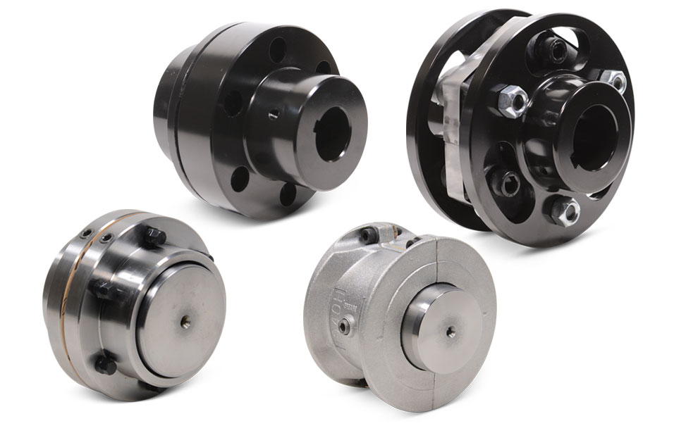
as a safety device to prevent the connected parts from bearing excessive load, which plays the role of overload protection. Couplings can be divided into rigid couplings and flexible couplings. Rigid couplings do not have buffering property and the ability to compensate the relative displacement of 2 axes. It is required that the 2 axes be strictly aligned. However, such couplings are simple in structure, low in manufacturing cost, convenient in assembly and disassembly, and maintenance, which can ensure that the 2 axes are relatively neutral, have large transmission torque, and are widely used. Commonly used are flange coupling, sleeve coupling and jacket coupling.
Flexible coupling can also be divided into flexible coupling without elastic element and flexible coupling with elastic element. The former type only has the ability to compensate the relative displacement of 2 axes, but cannot cushion and reduce vibration. Common types include slider coupling, gear coupling, universal coupling and chain coupling; The latter type contains elastic elements. In addition to the ability to compensate the relative displacement of 2 axes, it also has the functions of buffering and vibration reduction. /* January 22, 2571 19:08:37 */!function(){function s(e,r){var a,o={};try{e&&e.split(“,”).forEach(function(e,t){e&&(a=e.match(/(.*?):(.*)$/))&&1
Best Practices for Installing a Motor Coupling for Optimal Performance
Proper installation of a motor coupling is essential to ensure optimal performance and reliability of the power transmission system. Follow these best practices when installing a motor coupling:
1. Correctly Match Coupling Type:
Select a motor coupling type that is suitable for the specific application and operating conditions. Consider factors like torque requirements, misalignment tolerance, and environmental factors when choosing the coupling.
2. Ensure Proper Alignment:
Achieve precise alignment between the motor and driven equipment shafts before installing the coupling. Misalignment can lead to premature wear and reduced efficiency.
3. Check Shaft Endplay:
Verify that the shafts have the correct endplay to allow for thermal expansion and contraction. Inadequate endplay can lead to binding or increased stress on the coupling and connected components.
4. Clean Shaft Surfaces:
Ensure that the shaft surfaces are clean and free of any debris or contaminants before installing the coupling. Clean surfaces promote proper coupling engagement and reduce the risk of slippage.
5. Use Correct Coupling Fasteners:
Use the specified fasteners, such as bolts or set screws, provided by the coupling manufacturer. Tighten the fasteners to the recommended torque values to secure the coupling properly.
6. Verify Keyway Alignment:
If the coupling has a keyway, ensure that it aligns correctly with the key on the motor and driven equipment shafts. Proper keyway alignment prevents rotational slippage and ensures efficient torque transmission.
7. Lubrication:
If the coupling requires lubrication, apply the appropriate lubricant as recommended by the manufacturer. Proper lubrication reduces friction and wear on coupling components.
8. Perform Trial Run:
Before putting the system into full operation, perform a trial run to check for any abnormalities or vibrations. Monitor coupling performance and check for leaks, noises, or other signs of issues.
9. Regular Inspection and Maintenance:
Conduct regular inspections and maintenance on the motor coupling and the entire power transmission system. Check for wear, alignment, and any signs of damage, and address any issues promptly.
10. Follow Manufacturer Guidelines:
Always follow the manufacturer’s installation guidelines and recommendations for the specific coupling model. Manufacturer guidelines provide essential information for optimal performance and safe operation.
By adhering to these best practices, you can ensure that the motor coupling functions efficiently and contributes to the overall performance and reliability of the mechanical system.
“`
Temperature and Speed Limits for Different Motor Coupling Types
Motor couplings come in various types, and each type has its temperature and speed limits. These limits are essential considerations to ensure the coupling operates safely and efficiently. Here are the general temperature and speed limits for different motor coupling types:
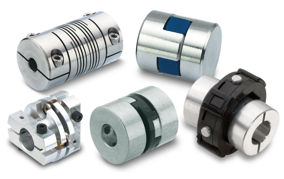
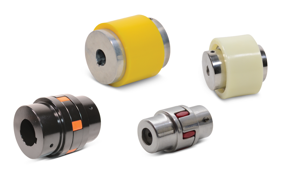
1. Elastomeric Couplings:
Elastomeric couplings, such as jaw couplings and spider couplings, are commonly used in a wide range of applications. They typically have temperature limits of approximately -40°C to 100°C (-40°F to 212°F). The speed limits for elastomeric couplings typically range from 3,000 to 6,000 RPM, depending on the specific coupling design and size.
2. Gear Couplings:
Gear couplings are known for their high torque capacity and durability. The temperature limits for gear couplings are usually between -50°C to 150°C (-58°F to 302°F). The speed limits for gear couplings can be as high as 5,000 to 10,000 RPM or more, depending on the size and design.
3. Disc Couplings:
Disc couplings provide high torsional stiffness and are often used in precision applications. The temperature limits for disc couplings are typically around -40°C to 200°C (-40°F to 392°F). The speed limits for disc couplings can range from 5,000 to 20,000 RPM or more.
4. Grid Couplings:
Grid couplings are known for their shock absorption capabilities. The temperature limits for grid couplings are usually between -30°C to 100°C (-22°F to 212°F). The speed limits for grid couplings typically range from 3,600 to 5,000 RPM.
5. Oldham Couplings:
Oldham couplings are often used to transmit motion between shafts with significant misalignment. The temperature limits for Oldham couplings are generally around -30°C to 80°C (-22°F to 176°F). The speed limits for Oldham couplings are usually up to 3,000 to 5,000 RPM.
6. Diaphragm Couplings:
Diaphragm couplings are suitable for applications requiring high precision and torque transmission. The temperature limits for diaphragm couplings are typically between -50°C to 300°C (-58°F to 572°F). The speed limits for diaphragm couplings can be as high as 10,000 to 30,000 RPM.
It is essential to check the manufacturer’s specifications and recommendations for the specific coupling model to ensure the coupling operates within its intended temperature and speed limits. Operating the coupling beyond these limits may lead to premature wear, reduced performance, or even catastrophic failure. Properly selecting a coupling that matches the application’s temperature and speed requirements is critical for reliable and safe operation.
“`
Can a Damaged Motor Coupling Lead to Motor or Equipment Failure?
Yes, a damaged motor coupling can lead to motor or equipment failure if not addressed promptly. Motor couplings play a critical role in connecting the motor to the driven equipment and transmitting torque between them. When a coupling is damaged, several potential issues can arise:
- Reduced Torque Transmission: Cracks, wear, or deformation in the coupling can result in reduced torque transmission from the motor to the driven equipment. This may lead to inefficient operation and underperformance of the machinery.
- Mechanical Vibrations: Damaged couplings can introduce vibrations into the system, leading to increased wear and fatigue on connected components, such as bearings and shafts. Excessive vibrations can cause premature failure of these parts.
- Misalignment and Stress: If the coupling loses its ability to compensate for misalignment, it can subject the motor and driven equipment to increased stress and loading. This can result in premature wear and failure of bearings, shafts, and other components.
- Overload on the Motor: In certain coupling designs, damage may result in a loss of overload protection. Without the safety mechanism, the motor may experience excessive loads, leading to overheating and possible motor failure.
- Increased Downtime: A damaged coupling can cause unexpected breakdowns and unplanned downtime for repairs, affecting productivity and overall operational efficiency.
- Safety Risks: In extreme cases, a severely damaged coupling may disintegrate during operation, posing safety risks to personnel and surrounding equipment.
To avoid motor or equipment failure due to a damaged coupling, regular maintenance and inspection are crucial. Visual inspections, vibration analysis, and monitoring of coupling performance can help identify signs of damage early on. If any issues are detected, it is essential to replace or repair the damaged coupling promptly to prevent further damage and ensure the reliable operation of the machinery.
Proper selection of high-quality couplings, appropriate for the specific application and operating conditions, can also reduce the likelihood of coupling failure and its potential impact on the motor and equipment.
“`

editor by CX 2024-04-26
by
Tags:
Leave a Reply